
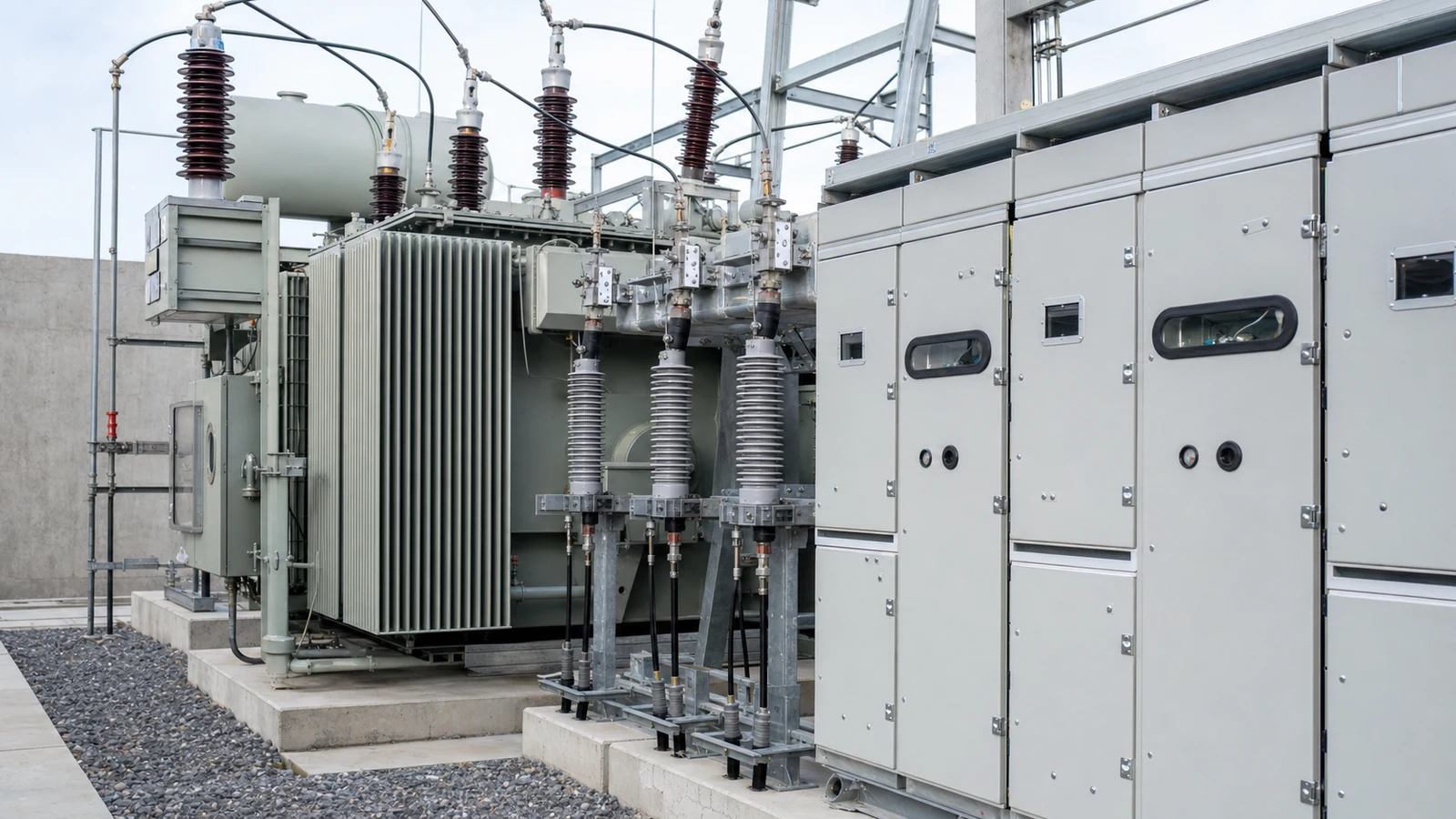
Surge Arresters in Transformer RFQs: Interface Checks
A transformer RFQ that says “with surge arresters” is still incomplete. It does not say which side of the transformer is protected, whether arresters are mounted at the transformer, inside the medium-voltage switchgear, at an overhead-line transition, or supplied by the utility, and it does not prove that the arrester duty matches the project’s insulation-coordination basis.
The short answer is: buyers should ask for the system voltage basis, required insulation level language, surge arrester scope, mounting location, terminal and cable interface, grounding path, monitoring or disconnecting devices if specified, drawings, and test or compliance evidence. Final selection remains subject to the project specification, utility rules, local code, applicable standards, supplier datasheets, insulation-coordination study where required, and qualified electrical engineering review.
This article helps procurement teams, EPCs, industrial plants, commercial buildings, mines, parks, utilities, and renewable-energy projects write clearer transformer and switchgear inquiries. It does not select arrester ratings, calculate protective margins, design grounding, replace lightning studies, or approve energization.
“With arrester” is not a technical boundary
Surge arresters are often treated as small accessories, but they sit at a high-risk interface. They may protect transformer terminals from lightning or switching overvoltages, help coordinate equipment insulation levels, or form part of a utility service requirement. They also bring practical questions about support brackets, clearances, cable terminations, disconnectors, counters, earth leads, testing, and who owns maintenance after handover.
For an oil-immersed transformer, arresters may be mounted near bushings or beside a cable box, depending on voltage class, site layout, utility practice, and the selected terminal arrangement. For switchgear, surge protection may be inside an incoming cubicle, associated with cable terminations, or defined as a separate scope. A buyer cannot compare quotations if one supplier includes arrester hardware and another assumes it is by the EPC or utility.
The first procurement rule is simple: name the protected equipment, name the location, and name the documents that will prove the assumption.
RFQ matrix for surge arresters and insulation coordination
Use this matrix to expose missing information before manufacturing drawings are frozen. It is not a universal design rule.
| RFQ item | What the buyer should state or request | Why it changes the order |
|---|---|---|
| System voltage basis | Provide nominal voltage, highest voltage for equipment where specified, frequency, earthing method, source type, and utility service information. | Arrester selection and insulation-coordination language depend on the system, not only the transformer kVA. |
| Insulation level language | State whether the project uses IEC, IEEE/ANSI, GB/GB/T, utility, or local terms such as rated withstand voltage, LIWV, SIWV, BIL, or power-frequency withstand. | Different markets use different terms. The quotation should not translate them into another system without project approval. |
| Protected equipment | Identify whether protection is required for transformer HV terminals, LV terminals, neutral, cable terminations, MV switchgear, capacitor bank, overhead-line transition, or complete substation package. | A generic “arrester included” note may protect a different point from the one the engineer intended. |
| Mounting location | Request an outline drawing showing arrester position, bracket, phase spacing, cable box or bushing relation, clearances, access, and replacement route. | The protective effect and installability are both affected by location and lead arrangement. Final dimensions must follow approved drawings and applicable rules. |
| Arrester duty data | Ask the supplier to state the quoted arrester type, rating basis, continuous operating voltage or equivalent term, energy or charge classification where applicable, and standard reference. | Buyers should avoid selecting values from a catalogue without the project study. Supplier assumptions must be visible for engineering review. |
| Grounding and lead path | Define earth terminal location, conductor responsibility, shield bonding, counter/disconnector location if specified, and connection to the site grounding grid. | Poorly defined grounding can create installation delays and may affect protection performance. Final grounding must follow project design. |
| Switchgear and cable interface | Provide single-line diagram, cable type, termination kit, CT/PT location, metering boundary, protection relay needs, and utility sealing requirements. | Surge protection often sits at the transformer-to-switchgear boundary. Use the cable box RFQ checklist when terminations are unclear. |
| Evidence and handover | Request datasheet, outline drawing, wiring or terminal list if devices are monitored, accessory list, test or compliance statement, manuals, packing list, and approved-deviation log. | The site team needs traceable evidence before installation and pre-energization checks. |
Transformer and switchgear packages must tell the same story
Many scope gaps appear when the transformer and switchgear are purchased separately. The transformer supplier may assume arresters are mounted in the MV cubicle. The switchgear supplier may assume transformer-mounted arresters. The EPC may expect the utility to provide them at the service entrance. Each assumption can be reasonable in one market and wrong in another.
For a compact substation, the RFQ should be more explicit because the package may combine MV switching, transformer, LV distribution, metering, cable compartments, enclosure, and earthing in one factory-built assembly. The buyer should ask whether arresters are included inside the MV compartment, near transformer bushings, at incoming cable terminals, or excluded for utility supply. If a surge counter, leakage-current monitor, disconnector, remote alarm contact, or inspection window is required, it should appear in the accessory schedule and drawings.
Do not solve this with a single phrase such as “standard lightning protection.” Building lightning protection, overhead-line shielding, surge arresters on power circuits, low-voltage SPDs, cable sheath bonding, and transformer insulation coordination are related but different topics. The responsible project engineer should define which layers are required.
Insulation level is not a sales claim
Insulation coordination asks whether equipment withstand levels and overvoltage protective devices are suitable for the expected electrical stresses. That can involve lightning surges, switching overvoltages, temporary overvoltages, earthing method, cable length, overhead-line exposure, transformer winding connection, breaker operation, capacitor banks, motors, renewable inverters, and utility fault behavior.
Procurement should not turn this into a broad promise that a higher insulation level solves every overvoltage concern. A higher insulation level may affect cost, size, testing, and compatibility, and it still does not replace the need for correct arrester location and grounding. A poorly placed arrester can leave long leads or cable sections exposed; a correctly placed arrester with the wrong project assumptions can still fail engineering review.
When the RFQ includes retrofit work, collect existing transformer nameplates, arrester records, switchgear drawings, cable route information, grounding drawings, utility requirements, and any previous failure or overvoltage records available to the project team. For renewable collection systems, mines, long overhead feeders, or weak networks, ask the engineer whether a specific insulation-coordination or transient study is required before purchase.
Standards help define the vocabulary
Standards are useful references, but the applicable market and project documents decide the final requirement. IEC 60071-1:2019 RLV describes insulation-coordination principles for three-phase AC systems above 1 kV within its stated scope. IEC 60099-5:2018 gives selection and application recommendations for surge arresters in three-phase systems above 1 kV. IEC 62271-200:2021 is relevant where AC metal-enclosed switchgear above 1 kV and up to 52 kV is specified.
Those references do not make IEC the default for every order. A project may instead use IEEE, ANSI, NEMA, GB/GB/T, utility specifications, national electrical code, grid code, owner standards, mining rules, fire rules, seismic rules, or local AHJ requirements. The RFQ should name the intended basis and require supplier documents for the exact equipment quoted.
RFQ wording buyers can adapt
“Please state whether surge arresters are included in the transformer, switchgear, compact substation, utility, or EPC scope. Identify the protected terminals, mounting location, grounding interface, accessory devices, and document evidence.”
“Arrester rating, insulation level, protective margin, temporary overvoltage duty, lead length, grounding, and final acceptance remain subject to the project specification, utility requirements, applicable standards, supplier datasheets, and qualified engineering review.”
“Submit outline drawings showing arrester location relative to transformer bushings, cable boxes, MV switchgear, cable terminations, earth terminals, access clearances, and replacement route before manufacturing release.”
“Do not assume that IEC, IEEE/ANSI, GB/GB/T, utility, or local insulation-level terms are interchangeable. Any deviation from the project insulation-coordination basis shall be listed for approval before order confirmation.”
A practical release rule
Do not release a transformer or substation order while surge arresters are hidden inside an accessory line. Before manufacturing starts, the buyer should know which equipment is protected, where the arresters are installed, who supplies and grounds them, what insulation-level basis is being used, what documents prove the assumption, and who approves the final coordination.
That rule does not make procurement responsible for high-voltage design. It makes the invisible interface visible early enough for the EPC, utility, supplier, and commissioning team to close it before installation.
