
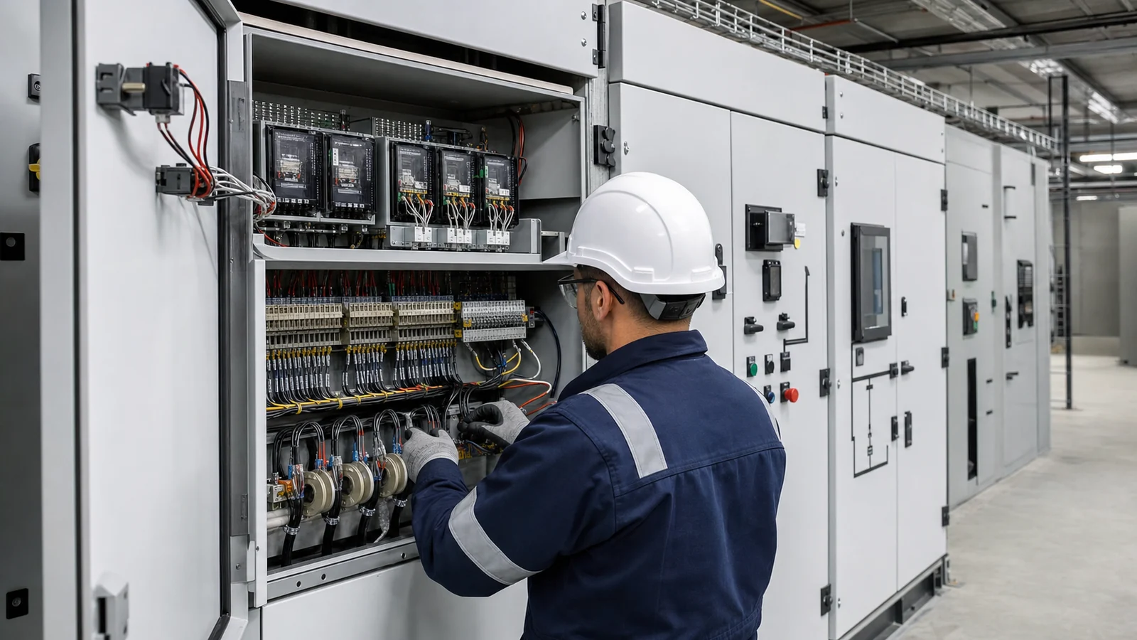
Protection CTs and Relays in Switchgear RFQs
A switchgear quotation can include breakers, busbars, cabinets, and meters while still leaving the protection system too vague for manufacturing approval. The missing details are often small words in the RFQ: CT ratio, CT class, burden, relay function, trip circuit, interlock, auxiliary contact, test terminal, communication point, and who is responsible for the final settings.
The short answer is: a switchgear RFQ should separate protection CTs from metering CTs, state relay and trip-circuit functions, define transformer and feeder boundaries, request drawings and terminal lists, and leave final settings to the project protection study. Final suitability still depends on approved single-line diagrams, short-circuit and protection coordination studies, utility requirements, local code, AHJ review, supplier datasheets, test records, and commissioning by qualified personnel.
Use this article as a procurement checklist. It does not design the protection system or replace a protection engineer.
Treat CTs and relays as engineered interfaces
Switchgear is not only a metal enclosure around switching devices. In transformer feeders, incomers, bus couplers, capacitor feeders, motor feeders, and compact substation panels, the protection and metering chain has several handover points: primary conductor, CT or VT, relay or meter, trip coil, auxiliary supply, terminal block, alarm output, SCADA or BMS point, and commissioning test position.
If those handover points are not defined, two quotations may look similar while carrying different technical risk. One supplier may include relay wiring and test blocks; another may include cabinet space only. One quote may assume protection CTs inside the MV switchgear; another may expect CTs in a transformer cable box or LV panel. These differences affect cabinet size, cable entry, delivery scope, factory testing, and site commissioning.
RFQ matrix for protection and metering scope
Use this matrix to make switchgear quotations comparable. It is not a universal design standard, and it should be adapted to the target market, project specification, and utility approval path.
| RFQ item | What the buyer should provide or request | Why it changes the order |
|---|---|---|
| Latest single-line diagram | Provide transformer, incomer, feeder, bus coupler, neutral, earthing, metering, and utility boundary information. | CT location and relay function cannot be reviewed from a cabinet list alone. |
| Fault-study basis | Provide available fault level, transformer data, operating modes, parallel transformer status, motor contribution if relevant, and study responsibility. | CT saturation review, breaker duty, and relay application depend on the system, not only the panel model. |
| Protection CT scope | State CT location, phase and earth-fault CT needs, ratio, accuracy class, burden, secondary current, terminal access, shorting provision, and whether values are final or for quotation only. | Protection CTs are selected for relay performance and fault duty. Generic CT language can make final settings difficult or impossible to approve. |
| Metering CT and VT scope | Separate utility metering, owner metering, power-quality meters, revenue requirements, VT fusing, test links, and sealable compartments where required. | Metering often follows utility or owner rules that differ from protection requirements. |
| Relay functions | List required functions by project terminology, relay model if specified, communication protocol if required, I/O count, trip logic, alarm outputs, and settings responsibility. | A relay nameplate does not prove that the logic, contacts, and wiring match the project protection philosophy. |
| Trip and control circuits | Define control voltage, AC or DC source, trip coil quantity, close coil, anti-pumping, lockout, interlocks, local/remote control, and supply supervision if specified. | Many site failures are wiring and control-power issues, not main-bus issues. |
| Test and isolation points | Request CT shorting terminals, test blocks, relay test access, terminal numbering, wiring diagrams, and safe isolation procedure for commissioning. | The site team needs a way to test without creating unsafe open-circuit CT conditions or undocumented wiring changes. |
| Documents and evidence | Request approved schematics, terminal lists, CT/VT datasheets, relay manuals, settings files if in scope, routine test records, packing list, and redline process. | The final protection chain must stay traceable from quotation through factory inspection and commissioning. |
Separate metering CTs from protection CTs
Metering and protection do different jobs. A metering CT should support measurement accuracy under normal operating conditions and within the applicable metering rule. A protection CT should support the relay’s ability to detect faults under the system conditions assumed by the protection study. One CT cannot be assumed suitable for both roles unless the project documents and supplier datasheets confirm it.
This is especially important when a project includes utility revenue metering, owner energy monitoring, power-quality meters, transformer differential protection, restricted earth-fault protection, feeder overcurrent, ground-fault protection, or capacitor-bank protection. The RFQ should say which CTs are included, where they are mounted, which terminals are brought out, and who approves the final ratio, accuracy, burden, and wiring.
If the project is also changing transformer capacity or impedance, send the protection RFQ together with the short-circuit current and switchgear rating checklist. Fault level, breaker duty, CT performance, and relay settings are connected decisions.
Trip circuits deserve the same attention as main ratings
Procurement discussions often focus on rated voltage, current, withstand current, and cabinet type. Those are necessary, but they do not prove that the panel can be operated, tripped, tested, and supervised as the project expects.
For medium-voltage feeders such as KYN28 switchgear, the RFQ should define protection relay functions, CT and VT compartments, trip and close coils, earthing switch interlocks, mechanical and electrical interlocks, alarm contacts, heater circuits, door contacts if used, and terminal strip layout. For low-voltage assemblies, the same discipline applies to ACB or MCCB trips, control relays, metering, incomer and bus-tie logic, capacitor feeders, and communication interfaces.
Control voltage is a common hidden assumption. A cabinet designed around one auxiliary supply may not match a site that uses a different DC system, UPS-backed AC control supply, or BMS input voltage. The RFQ should ask suppliers to state assumptions rather than letting them become late-stage wiring changes.
Coordinate transformer, grounding, and switchgear boundaries
Transformer protection is rarely contained in one supply package. The transformer supplier may provide temperature alarms, pressure devices, Buchholz contacts, neutral terminals, cable boxes, or marshalling terminals. The switchgear supplier may provide CTs, relays, trip coils, meters, auxiliary relays, and terminals. The EPC or protection engineer may provide settings and final trip logic.
Because of that split, the RFQ should define signal and protection boundaries early. Where neutral grounding affects ground-fault protection, use the neutral grounding RFQ checklist as a companion. Where a transformer, MV switchgear, LV board, and enclosure are bought as one compact substation, require a combined terminal list and internal wiring diagram, not separate catalogue descriptions.
The practical risk is not only wrong equipment. It is also unclear responsibility: a relay input with no source signal, a trip contact with no approved logic, a CT installed in the wrong compartment, or a meter that the utility will not accept.
Standards help language, but project documents decide settings
Standards can help buyers and suppliers use the same vocabulary. IEC 61869-2 is a relevant IEC reference for current transformers where that framework applies. IEEE C37.2-2022 provides device function numbers, acronyms, and contact designations used in protection and control documentation. For metal-clad switchgear in IEEE-oriented projects, IEEE C37.20.2-2022 is one relevant equipment reference within its scope.
These references are not interchangeable global requirements. A project may use IEC, IEEE, ANSI, NEMA, GB/GB/T, utility, fire, seismic, mining, renewable-energy, owner, or local AHJ requirements. The RFQ should name the applicable market and project documents. Relay settings, protection coordination, CT saturation checks, trip tests, and energization approval should be confirmed by qualified engineers using the final system data.
RFQ wording buyers can adapt
“Please quote the switchgear based on the attached single-line diagram, transformer datasheet, fault-study basis, protection philosophy, metering requirements, control-power arrangement, and project specification. Identify all assumptions and missing data.”
“For each incomer, transformer feeder, bus coupler, outgoing feeder, capacitor feeder, and spare feeder, state CT and VT location, ratio, accuracy class, burden, secondary wiring, test or shorting terminals, relay or meter function, trip circuit, alarm contacts, communication points, and terminal numbers.”
“Protection settings, CT saturation review, ground-fault logic, metering approval, utility acceptance, local code compliance, and AHJ review remain subject to the project electrical design and final approved documents.”
“Before manufacturing, submit the general arrangement, single-line diagram, schematic diagram, terminal list, CT/VT datasheets, relay list, point list, control-power diagram, routine test scope, and document revision procedure for approval.”
A practical decision rule
Do not release a switchgear order because the quote says “protection relay included.” Release it only when the CT locations, metering boundaries, relay functions, trip circuits, control power, test terminals, documents, and approval responsibilities are written down.
That does not turn procurement into protection engineering. It gives the engineer, supplier, utility, and commissioning team enough information to confirm the design before the switchgear becomes a finished cabinet.
